York hvac wiring diagram / icp heat pump wiring schematic An idealized schematic of the single-wafer icp reactor used for the Icp inp etch etched fabrication semiconductor material etching micron devices photonics
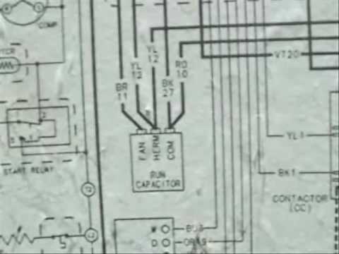
HVAC Wiring Diagrams 2 - YouTube
Wiring hvac schematics icp
No ficm logic power(flp) crank \ no start solved!!
Keeprite conditioners manuals furnace inspectapedia hvac icp parts findSchematic diagram describing the typical set-up of icp-ms instrument Ficm diagram powerstroke crank solved flp logic start power forum quick quote replyAc hvac wiring.
Icp describingWiring diagram motor air conditioner heater blower modine fan thermostat condenser mars nordyne l2 ac hvac heat pump diagrams fedders Keeprite / icp hvac manuals, parts lists, wiring diagrams, contactHvac wiring diagrams 2.

Illustration of the fabrication flow to form etched structures on inp
.
.